The Fab Academy 2014
Digital Fabrication Laboratory. Department of Architecture.
Institute of Technology. EPS-CEU San Pablo CEU University
Adolfo Gutiérrez Sánchez
Architect
The Fab Academy 2014 Digital Fabrication Laboratory. Department of Architecture. Institute of Technology. EPS-CEU San Pablo CEU University |
Adolfo Gutiérrez Sánchez Architect |
|||
| Home | Portfolio | Files | ||
| 3D PRINTING |
|
The assignment The assignment for this week was to model a piece that later we eill print on the 3D printer. One of the requierements for the design was that the piece could not be fabricated with other methods as extraction with the CNC machine or with laser cutting. As I am always thinking on the final project pieces, and in my design of the reactive roof. One of my desires is that all the louver pieces of the roof move together with the engine. I thought about the design of some gears that move with a chain, in the same way as a bike moves with its gears. The piece of the chain suits perfect with the assignment. |
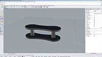
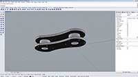
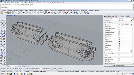
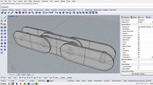
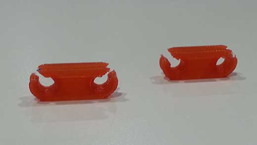
The chain design I was inspired in the bike chain, as it works perfectly with the gears and it will be the shape that less problems will give to me in the engine. This design was simplified in order to be printed easily in the 3D printer, but the essence was still the same: some articuladed shackles that will be printed one inside the other one so the final result is not possible to do with a conventional method. The two pieces of the chain adapt perfectly one to the other and with and easy design the problem is resolved. |
 |
 |
 |
||
|
||
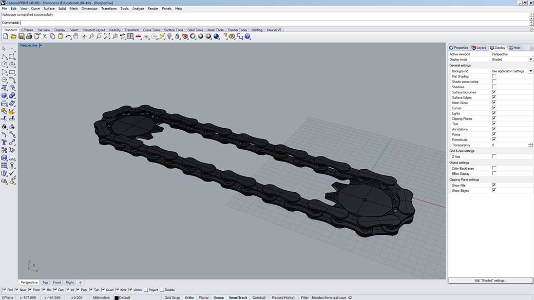
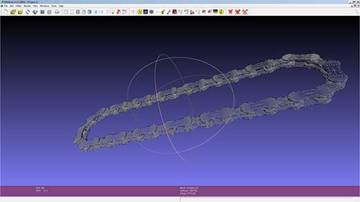
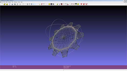
The mesh creation: from Rhino to STL Rhinoceros is a very nice program optimized for direct link into a 3D printer software, so at this level, just saving the project as a .stl file is enought o convert the NURBS object into a mesh and to get ready to print with the Replicator 2 software. As I have two different pieces in my engine: the chain and the gears, I created two separated files aswell to prepare them in the MeshLab. I am not use to manipulating meshes in Rhino nor any other program, as I have been always using NURBS and solids. The only parameter that I had to change in the conversion was decididing that the level of detail was maximum of 1 mm. Atending to my instructor advice, I had to review some important consideratiosn between the printing: - Solid objects: before the conversion into a mesh, it is important to consider that the object is a solid object and no separated surfaces. - Surface Normals.- check all the surface normals that are oriented into the same direction. - Holes and open edges.- the holes have to be closed faces, if they are empty faces, the printer will advice with an error. - Manifold object.- non-manifold objects will not be printed in the 3D printer - Duplicate surfaces.- avoid to have duplicate surfaces in the model - Floating objects.- it is not possible to print floating objects, however, as I have in my model a connection that needs to be articulated after the printing, some tricks can be done in order it to work, as the printing of some small supports that can be broken afterwards. - Large models.- they should be sliced into separated models - Wall thickness.- it has to be set as minimum of 1mm - Surface quality and orientation.- the orientation of the surfaces is important in the strength of the faces of the printing - Support.- a thin slice should be put in the base of the object in order it does not move and maintains firm - Fit tolerances.- it is important in objects that have interlocking parts - Thread width.- depending on the 3D printer you are using, some width or another will be suitable - Scaling down.- if you scale down the object directly on the 3D printer software, beware of maintaing the wall thickness so it does not break down
|
|
 |
 |
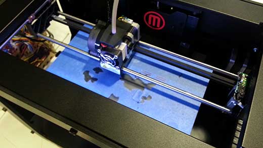
The 3D printing The final step of this subassignment is the real printing. As it is my first try, and even I have done all the considerations of my instructor, printing an articulated object for the first time will be complictaed, and I expect some problems from the beginning. |
|
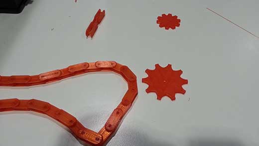
I had some problems with my first try of 3D printing. I had to make some changes of the piece before printing, as I was not printing it in the correct orientation. I turned the chain upside down, but then some problems came: - I had to redesign the borders of the chain shackles, as they have to touch the floor for a correct printing - I had to make some singular pieces that may connect stretches of the chain because prinitng in this direction was not possible to print the whole piece of the chain already closed, so I modelled two singular pieces of this shape as I had a desired size of chain the double as the maximum printable of the Replicator 2 by MakerBot. Done that, I kept going with the design of the gear, and it was not necessary to redesign the whole gear as the distances and the functioning of the rest of the piece was the same. |
|
 |
 |
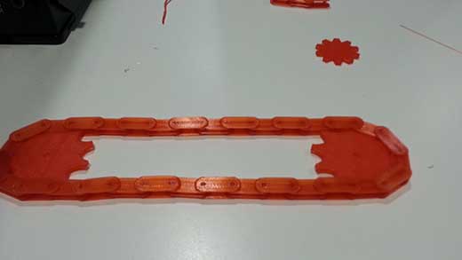
Finally, once we have done all the design changes, I am decided to print the different files. This is just a step to approach the final project, but once I have the gears working, it will help me a lot in the final construction of my project. The 3D printing went very good, I did not have any problems during the printing. I divided the prinitng into some steps, and assemble all of them ath the final moment. Here are some of the images of the printed elements: |
|
 |
 |
 |
 |
3D SCANNING |
|
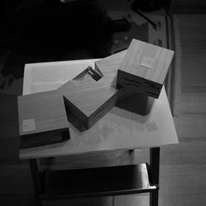
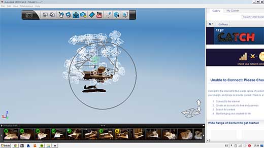
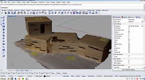
The assignment The second sub-assignment, consists of the 3D scanning of an object. As we don't have any 3D scanner options that Neil gave us, the only solution that I had was actually to use a software based on the reconstruction of a 3D mesh by the pictures in many angles and positions of an object. The chosen object, after some failed attempts, was a medium size model made in wood that had mane holes in the facade and some sidesteps in the floorplan, that may be helpful for the scanning. I chose the Autodesk software, as I had used already before, and the compatibility with the software that I am used to work with (AutoCAD, Revit, Navisworkws..) is very optimized. After some fails, I searched for some helpful advice that will help me in the creation of the mesh: - I put some stick notes in yellow that served a references in the scanning - I put a base taht was not a solid color, so the scannig is forced to follow the pattern from the surface - I elevated the platform in a portable stair so the process of making the pictures was easier for me. |
 |
 |
 |
 |
|
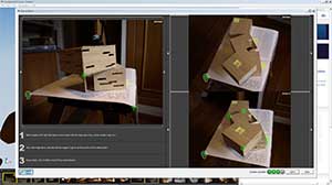
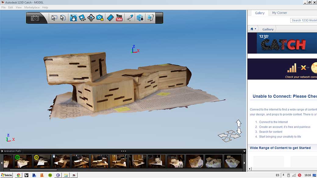
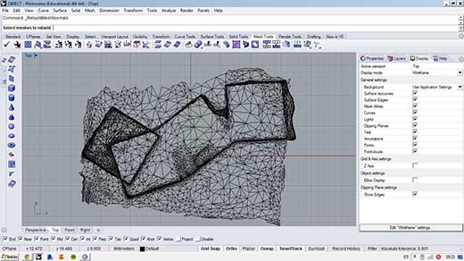
The scanning Following the instructions of the software, and with a proper camera, I scanned the whole model from different points of view. I had some bad luck that day as it rained, and my idea was to do the pictures outside, so the light was not as good as I expected, and there were some errors in the scanning, as the corners of the model where not very fixed. After taking the pictures and letting the program do its work, we can do some postproduction of the mesh and adjusting some corners for a better result of the mesh. With the job done, most of it by 123D CATCH software, we can export the object as a mesh and open it in other software. I exported it as a .obj (OBJECT) and opened it in Rhinoceros, were I am more comfortable. The result of the scanning was quite good, and I was very happy with it. I might try to get better results if I take the pictures in a sunny day in outside in my garden. I will report it with pictures of the results |
|
 |
 |